The Ultimate Guide to Understanding Valve Symbols

Valve symbols are the shorthand of engineering, a language that allows professionals across the globe to communicate complex ideas through simple, standardised representations. These symbols are not just drawings; they embody the functionality, type, and operation of valves in piping and instrumentation diagrams (P&IDs), making them indispensable in the fields of mechanical, chemical, and civil engineering. This comprehensive guide is designed to unravel the complexity of valve symbols, ensuring that you, the reader, are well-versed in identifying and understanding these critical components in any engineering blueprint.
Introduction to Valve Symbols
Valves are mechanical devices that control the flow and pressure within a system or process. They are essential components in various industries, including oil and gas, water treatment, and manufacturing. To effectively represent these valves in diagrams, engineers use specific symbols that denote the type of valve, its operation mechanism, and additional functionalities. Understanding these symbols is crucial for designing, operating, and maintaining industrial systems efficiently.
The Importance of Valve Symbols in Engineering
Understanding the importance of valve symbols in engineering goes beyond merely recognising the shapes and lines on a schematic. These symbols are foundational to the creation, maintenance, and troubleshooting of complex systems across a variety of industries. Let's delve deeper into why these symbols hold such significance in the engineering world.
Universal Language for Global Collaboration
Valve symbols form a universal language that transcends cultural and linguistic barriers, enabling engineers, technicians, and professionals from different parts of the world to collaborate effectively. This shared language ensures that irrespective of one's native language or geographical location, the design and function of a system can be understood, constructed, and maintained. In an era of global engineering projects and multinational companies, this common language facilitates seamless international collaboration.
Precision and Clarity in Design
Engineering projects demand precision, and the use of standardised valve symbols contributes significantly to this requirement. Each symbol encapsulates specific information about the type of valve, its operation, and its role within a system. This precision prevents ambiguities that might arise from textual descriptions, ensuring that every individual involved in a project has a clear and accurate understanding of the system's design.
Efficiency in Communication
The use of valve symbols makes communication more efficient among project team members. Instead of lengthy descriptions, a simple symbol can convey a wealth of information. This efficiency is crucial in fast-paced engineering environments where time is of the essence, and it helps in speeding up the design, approval, and implementation phases of projects.
Basic Valve Symbols
 | Gate Valve | A gate valve is a type of valve used to start or stop the flow of fluid in a piping system, but it is not designed to regulate the flow. It operates by lifting a gate (or wedge) out of the path of the fluid. The gate's movement is perpendicular to the direction of flow, which means the valve operates in a fully open or fully closed position, making it an excellent choice for applications where a straight flow of fluid and minimal restriction is desired. |
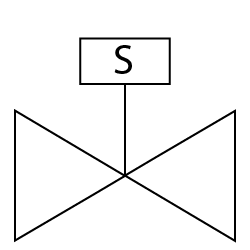 | Solenoid Valve | A solenoid valve is an electromechanically operated valve, widely used to control the flow of liquids or gases in a system. The operation of a solenoid valve is driven by an electric current through a solenoid: in the simplest case, this solenoid is a coil of wire that becomes magnetised when an electric current passes through it. The magnetic field generated by the solenoid actuates the valve mechanism, either opening or closing it to control the flow of fluid. |
 | Butterfly Valve | A butterfly valve is a type of flow control device, commonly used to regulate a fluid flowing through a section of pipe. It is named for its butterfly-like appearance when the valve is open, consisting of a metal disc mounted on a rod. When the valve is closed, the disc is turned so that it completely blocks off the passageway; when it is open, the disc is rotated a quarter-turn to allow fluid to pass through. The simplicity of this mechanism makes butterfly valves efficient, cost-effective, and suitable for a wide range of applications. |
 | Ball Valve | A ball valve is a form of quarter-turn valve which uses a hollow, perforated, and pivoting ball (called a "floating ball") to control flow through it. It is open when the ball's hole is in line with the flow and closed when it is pivoted 90-degrees by the valve handle. The handle lies flat in alignment with the flow when open, and is perpendicular to it when closed, making for easy visual confirmation of the valve's status. |
 | Check Valve | A check valve, also known as a non-return valve, one-way valve, or clack valve, is a type of valve that allows fluid (liquid or gas) to flow through it in only one direction. Check valves are used in a wide range of applications to prevent backflow, which could potentially cause damage to equipment or undesirable mixing of fluids. They are critical components in ensuring the safety and efficiency of many systems, including water and sewage systems, fuel delivery systems, and in various types of industrial processing equipment. |
 | Plug Valves | A plug valve is a type of flow control valve that allows the user to regulate flow by rotating a cylindrical or tapered plug within the valve body. This plug contains one or more hollow passageways going sideways through the plug, so that fluid can flow through the plug when the valve is open. The simplicity of the design and the ability to maintain a tight seal make plug valves a popular choice for a wide range of applications. |
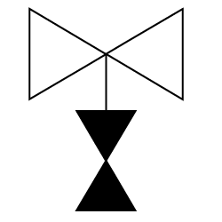
 | Relief Valves | A relief valve is a type of safety valve used to control or limit the pressure in a system; it prevents the system pressure from exceeding a designated safe maximum. When the system pressure reaches the valve's setpoint, the valve opens to allow the excess fluid (which can be gas, liquid, or a mixture of both) to escape, thereby preventing potential damage to the system from overpressure. |
 | Safety Valves | A safety valve is a critical component in various systems and equipment, designed to automatically release substances from a boiler, pressure vessel, or other system when the pressure or temperature exceeds preset limits. Its primary function is to ensure the safety of operations by preventing potential explosions, equipment failures, or hazardous situations that could result from excessive pressure buildup. |
 | Check Stop Valves | A check stop valve is a specialised type of valve that combines the features of a check valve with those of a stop valve. This combination offers both flow control and backflow prevention within a single valve body, optimising space and simplifying system design. Let's break down the components and functionalities of a check stop valve to understand its operation and applications better. |
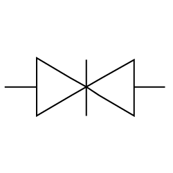
 | Diaphragm Valves | A diaphragm valve is a specialised type of valve that controls fluid flow by the movement of a flexible diaphragm. This diaphragm is pressed against a seat or weir to open or close the valve and regulate the flow of fluid. Diaphragm valves are particularly useful for handling corrosive fluids, viscous fluids, or fluids that contain suspended solids, due to their streamlined flow path and minimal internal crevices. |
 | Angle Valves | An angle valve, a fundamental component in plumbing and industrial systems, is designed to regulate the flow of fluid (which can be liquid or gas) by changing the direction of the flow at a 90-degree angle. This distinctive feature not only allows for precise control over the flow rate but also helps in reducing the system's pressure drops, making angle valves especially useful in applications where space is limited or a directional change in the piping is required. |
 | Block & Bleed Valves | A block and bleed valve is a critical component in various piping systems, designed to isolate or block the flow of fluid (gas or liquid) in the system and to bleed off or vent the pressure from the valve's upstream side. This configuration allows for safe maintenance, calibration, or repair of system components downstream of the valve without needing to shut down the entire system. The ability to isolate a section of the system while safely venting trapped pressure significantly enhances operational safety and system efficiency. |
 | Knife Gate Valve | A knife valve, also known as a knife gate valve, is a type of valve designed for on-off and throttling services, particularly effective in handling slurry, viscous, corrosive, and abrasive media. Its distinguishing feature is a sharp, knife-like gate made of metal that slides into the valve seat to provide a tight shut-off. This gate can cut through thick fluids and solids that may be present in the flow, making knife valves particularly useful in applications involving pulp and paper, mining, wastewater treatment, and chemical industries. |
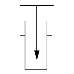
 | Needle Valves | A needle valve is a type of valve with a small port and a threaded, needle-shaped plunger. It allows precise regulation of flow, although it is generally only capable of relatively low flow rates. The design of the needle valve provides a very accurate control of the flow rate. The distinctive feature of a needle valve is the long, tapered, needle-like point on the end of the valve stem. This "needle" fits into a seat. Because of the delicate nature of the design, even a slight turn of the handle can significantly change the position of the needle, allowing for precise flow control. |
Reading P&ID with Valve Symbols
Reading Piping and Instrumentation Diagrams (P&IDs) with valve symbols is a fundamental skill for engineers, technicians, and operators involved in the design, operation, and maintenance of industrial plants. P&IDs provide a detailed graphical representation of the piping and the equipment involved in the process, including valves, sensors, pumps, and other components. Understanding how to read these diagrams enables professionals to gain insights into the process flow, operational control, and safety mechanisms of a plant. Here's an expanded view on how to effectively read P&IDs with a focus on valve symbols.
Understanding the Basics of P&IDs
P&IDs are complex diagrams that include various symbols and notations. Before delving into valve symbols specifically, it's crucial to familiarise yourself with the basics of P&IDs, including:
- Lines: Represent piping and show the direction of flow.
- Equipment Symbols: Indicate the types of equipment used in the process, such as pumps, tanks, and heat exchangers.
- Instrumentation: Shows sensors and instruments used to measure and control the process, like temperature and pressure gauges.
Identifying Valve Symbols
Valve symbols on P&IDs are standardised, allowing for consistent interpretation. Each type of valve has a unique symbol that represents its function and operation. Key steps to identifying valve symbols include:
- Learn the Basic Valve Symbols: Familiarise yourself with the symbols for common valves, such as ball valves, gate valves, globe valves, check valves, and butterfly valves. Each has a distinctive shape that reflects its operational mechanism.
- Understand Actuator Symbols: Valves may be operated manually or by actuators. Actuator symbols, such as a square for a solenoid or a triangle for a pneumatic actuator, are often shown together with the valve symbol to indicate the method of operation.
- Recognise Specialty Valves: Beyond the basics, there are symbols for specialty valves, such as pressure relief valves, needle valves, and diaphragm valves. Learning these symbols helps in understanding more complex systems.
Valve State Symbols
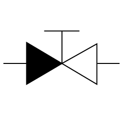 | Special Purpose Valves | A special purpose valve is a type of valve specifically designed to perform unique functions or handle specific conditions that go beyond the capabilities of standard valves like gate, globe, check, and ball valves. These valves are tailored to meet the precise requirements of particular applications, often involving extreme pressures, temperatures, or corrosive materials, as well as to ensure safety, reliability, and efficiency in specialised systems. The design, materials, and operation of special purpose valves can vary widely depending on their intended use. |
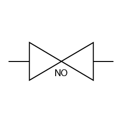 | Normally Open (NO) Valves | A normally open (NO) valve is a type of valve that is open when in its default, unactuated, or rest position. This means that the valve allows flow through it without any external force or actuation applied. When actuated, either manually or by an automatic actuator (such as pneumatic, hydraulic, or electric), the valve closes, stopping the flow. The term "normally open" refers to the valve's default state, not its state during operation. |
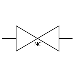 | Normally Closed (NC) Valves | A normally closed (NC) valve is a type of valve that remains closed when it is in its default state, meaning no external force or power is applied to it. This default state ensures that the flow of fluid (liquid or gas) through the valve is blocked until an actuating force, such as manual effort, electrical energy, or pneumatic pressure, is applied to open it. The design principle of a normally closed valve is crucial for safety and control in various applications, where it is essential to prevent the flow unless specifically commanded to allow it. |
Conclusion
Valve symbols are more than just icons on a page; they are the language of engineering, crucial for the design, operation, and maintenance of systems across a multitude of industries. This guide has walked you through the basics and complexities of valve symbols, from their importance in engineering communication to their practical applications in the field. Whether you are a seasoned engineer or a newcomer to the world of industrial design, mastering valve symbols is essential for success. By understanding these symbols, you ensure that your projects flow smoothly, literally and figuratively. Embrace this language, and you will open doors to clearer communication, efficient design, and operational excellence in any engineering endeavor.
FAQs
1. What does a valve symbol on a P&ID indicate?
A valve symbol on a P&ID indicates the presence of a valve in the piping system, its type, and its function. Each symbol is standardised to represent different types of valves, such as ball, gate, globe, check, and butterfly valves. These symbols provide quick information about how the valve operates (e.g., turning, lifting, or sliding), its method of actuation (manual, electric, pneumatic, hydraulic), and any special features (e.g., throttling, non-return, pressure relief).
2. How can I differentiate between different types of valve symbols?
Differentiating between valve symbols involves recognising the basic shapes and additional marks that signify the valve's operation and function. For example:
- Gate valves are represented by a simple gate symbol, signifying an on-off operation.
- Globe valves show a spherical shape, indicating they can regulate flow.
- Check valves are depicted with a single dash and an arrow, pointing out the flow direction and their function to prevent backflow.
- Ball valves feature a solid or hollow circle, showing their spherical closure element. Learning these symbols and their variations can help in quickly identifying the valve type on a diagram.
3. What does it mean when a valve is shown as 'normally closed' or 'normally open' on P&IDs?
On P&IDs, a valve being "normally closed" (NC) or "normally open" (NO) refers to its default state when there's no power or actuating force applied. A normally closed valve blocks the flow under normal conditions and opens when activated, while a normally open valve allows flow until it is actuated to close. These states are crucial for understanding the system's operation, especially in terms of safety and process control.
4. Are valve symbols on P&IDs the same across all industries?
While there is a high degree of standardisation in valve symbols across industries, there can be slight variations in symbols or additional notations based on industry-specific practices, regional standards, or company-specific guidelines. However, the basic principles and symbol shapes remain consistent, ensuring general comprehensibility. It's always advisable to refer to the legend or key provided with the specific P&ID you are working with.
5. What are valve symbols and why are they important in engineering drawings?
Valve symbols are graphical representations of various types of valves used in piping and instrumentation diagrams (P&IDs) and other engineering schematics. They are crucial for providing a clear and concise way to communicate the types, positions, and functions of valves in a system, ensuring accurate construction, maintenance, and troubleshooting.
Thank you for reading! Learnt something new? Consider subscribing to the End Connections newsletter below to stay up-to-date with all valve, actuator, & industrial-related news.

